Adding ultra-low and ultra-high circuits to an Ampeg B-12N amp
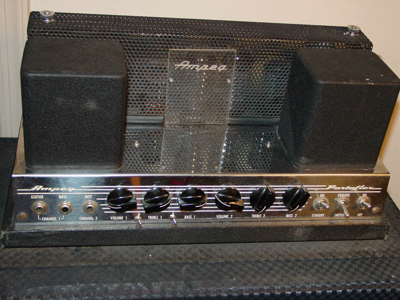
I made this modification to channel one (guitar/bass) of my 1968 B-12 with excellent results. The amp has an even warmer and clearer sound. I play 4 and 5-string electric and upright basses through this amp in small combo settings and theatres. I pretty much always use the amp with the low and high tone circuits on. The amp has been working with this modification since 1992 without a problem.
I took this tone circuit design from a B-15 amp which is very nearly electronically identical to the B-12. I'm not sure if Ampeg ever produced the B-12 with this option - I have seen B-15's with and without it. If you try this, I hope you enjoy it as much as I have. Oh, please be careful doing this. These amps can be extremely dangerous to work on because of the voltages and circuits used. If you have any doubts, take this job to a professional.
Parts:
Capacitor - .01MF
Capacitor - .02MF (I used a .018)
Capacitor - .1MF
Resistor - 39K
Resistor - 1M
Switch - single-pole, single-throw (2)
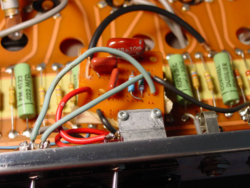
PC board - I used a small project board from Radio Shack (#276-159A) with a few printed circuits to connect components
Medium gage wire
Soldering iron and solder
Shielded audio wire - 1 conductor plus shield
L-bracket - I made one from a strip of metal I had - about 1" wide x 2.5" long, bent half way
2 small nuts and bolts to attach pc board to bracket.
Schematics:
My B-12's Schematic (1.3MB) for reference. You should check this against the schematic in your amp if you are thinking of making this mod. When I searched, I didn't find any other preamp design for a tube-based B-12, but to be safe...
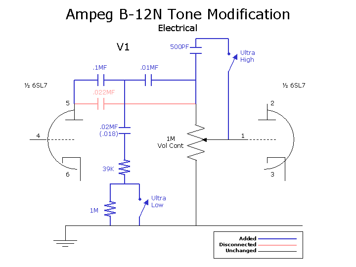
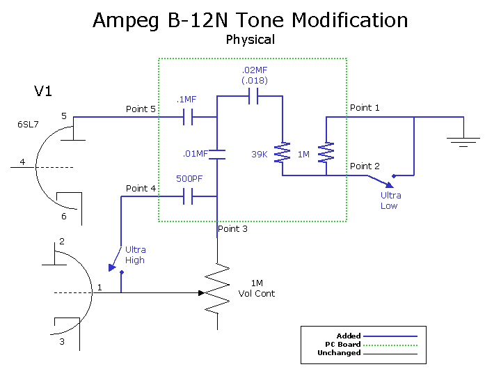
In the electrical schematic below, I have added the parts in blue in place of the one capacitor marked in red. The physical schematic shows the rough placement of the components on the pc board.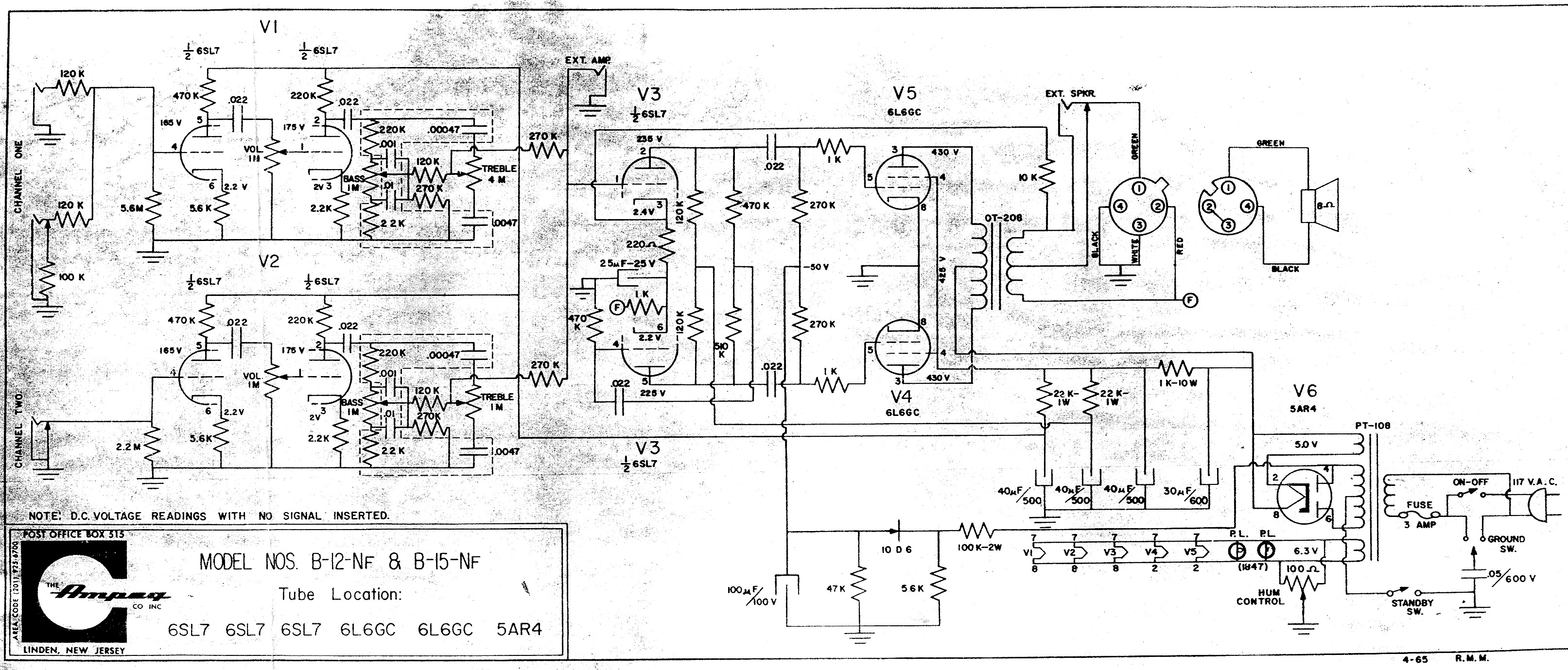
Assembly:
The pc board I used has enough generic printed conductors to make assembly fairly straight forward.
- Assembly Stages
- Mounting bracket
The mounting bracket is mounted under the channel one Volume pot, so it will need a large enough hole to accomodate the pot shaft. The other end of the bracket (and the pc board) will need two small holes for the small nuts and bolts to be used to mount the pc board.
- Unmount the Volume pot from the chassis
- Prepare all the holes and mount the pc board on the bracket. - Component placement
- Solder the components onto the pc board. Be careful not to connect the circuit to any printed conductors that might connect to the mounting bracket! When fully mounted, the bracket will be ground. - Switches
- Drill holes for the switches on the front face of the amp. Be very careful not get metal shavings in the amp - use a vacuum cleaner while drilling. I placed the ultra-high below and between the volume and treble pots and the ultra-low between the treble and bass pots. They must be placed high enough from the bottom edge of the face to clear the mounting platform's lip. - Final assembly
- Make the following connections from the pc board to the amp (See the physical schematic above for reference to the "Points" listed below):
- Point 1 - Connect to both the chassis and the ultra-low switch
- Point 2 - Connect to the other side of the ultra-low switch
- Point 3 - Connect to the end of the Volume pot that connects to the capacitor that is to be removed from the circuit (see the electrical schematic above). Remove the wire from the Volume pot to the capacitor removing it from the circuit.
- Point 4 - Connect to the ultra-high switch. Connect the other end of the ultra-high switch to the center (wiper) of the Volume pot.
- Point 5 - Connect via shielded wire to pin 5 of vacuum tube 1 (V1 - a 6SL7). I did this at the end of the capacitor that is disconnected from the circuit rather than at the tube socket itself. I connected the shield on the PC board to ground (Point 1), but not on the other end to prevent a ground loop.
- Mount the pc board under the volume pot
- Mount the ultra-low and ultra-high switches